If you’ve ever sized a permanent magnet DC (PMDC) motor for an application that needs to get moving fast—say, a robotic arm lifting a full payload, a conveyor belt starting under a full load, or a mobility scooter pulling a steep ramp—you know the frustration of a motor that just can’t muster enough starting torque. As a PMDC motor supplier, I talk to engineers and design teams every week who run into this exact problem: they’ve picked a motor that works great for steady-state operation, but it just doesn’t have the oomph to overcome static friction at startup. Starting torque is the measure of a motor’s torque at zero speed, and for PMDC motors, it’s directly tied to the fundamentals of how these machines work. Today, I want to break down exactly what drives starting torque in PMDC motors, and actionable, practical steps to boost it—all from the perspective of someone who’s spent years helping clients solve these exact challenges. Permanent Magnet DC Moto
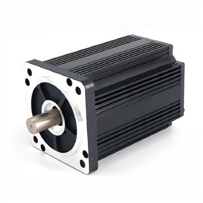
First, let’s get the basics straight. A PMDC motor generates torque by interacting between the magnetic field from the permanent magnets (stator) and the current flowing through the armature windings (rotor). The core formula for torque in any DC motor is T = K * I * Φ, where T is torque, K is a constant based on motor design, I is armature current, and Φ is the flux from the stator magnets. For starting torque, since speed is zero, there’s no back EMF (electromotive force) to limit current—so this formula is especially critical here. At startup, the motor isn’t spinning, so the armature isn’t generating the countervoltage that normally restricts current during operation. That means starting torque depends almost entirely on how much current you can push through the armature, and how strong the permanent magnet flux is. That’s the foundation, and every solution I’m going to cover circles back to these two variables: current and flux.
Let’s start with the most straightforward adjustment that many engineers overlook: adjusting the supply voltage at startup. Wait, I know what you’re thinking—if you increase voltage, won’t you burn out the motor? Not always, and here’s why. At startup, back EMF is zero, so the current draw from the motor is I = V / R_a, where R_a is the armature winding resistance. That means if you double the supply voltage from 12V to 24V, double the current flows—and torque is directly proportional to current, so torque doubles too. Of course, you can’t run at 24V constantly, because the current would overheat the armature and windings over time. But applications only need that high torque for a fraction of a second at startup. For example, a power window motor only needs extra torque to get the window moving, then it can run on a lower, steady voltage. This is called “start boost” and it’s a common trick we recommend for clients with intermittent high startup loads. We’ve had a client building agricultural seed drills that used a standard 12V PMDC motor, but their seed hoppers would get clogged with wet seeds, requiring 30% more torque at startup. Instead of swapping to a larger, more expensive motor, they added a simple capacitor-based circuit that delivers a 24V surge for the first 500 milliseconds of operation. That was enough to break the static friction, reduce their current draw by 15% overall, and saved them $120 per unit in motor costs. It’s a cheap, low-effort fix that works surprisingly well for a lot of applications.
Next, and more impactful, is optimizing the permanent magnet design. Φ, the flux term in the torque formula, is directly from the stator magnets. Not all permanent magnets are equal, and swapping to a higher-grade magnet can give a huge boost in starting torque without changing the motor’s size. For example, a standard neodymium magnet (N35 grade) has a residual flux density of around 1.2 Tesla, while a stronger N52 grade hits 1.48 Tesla—almost a 25% increase in flux. That translates directly to a 25% increase in torque, all with the same motor frame size and winding setup. But it’s not just the grade of magnet; it’s how you integrate it into the stator. Many PMDC motors use surface-mounted magnets on the stator housing, but if you switch to interior permanent magnets (IPM) or adjust the magnet’s shape to create a more uniform or concentrated flux gap, you can boost Φ even more. I should note: this isn’t a one-size-fits-all swap. We worked with a robotics client last year who wanted to upgrade their small 6V PMDC motor for a robotic gripper. They initially wanted to jump to N52 magnets, but when we ran simulations, we found their motor’s stator housing was too small to fit a full N52 magnet without reducing armature winding space. The result would have been a drop in armature current, negating the magnet gain. Instead, we used a custom-shaped N45 magnet that was slightly thicker in the poles where the flux interacts with the armature, and kept the winding size the same. That gave them a 18% increase in starting torque without any change to the motor’s footprint or price. It’s a balance between magnet strength, stator space, and winding capacity that requires working with a supplier who can customize the magnet design, not just off-the-shelf parts.
That leads us to another key lever: increasing armature current, which ties back to the torque formula. But how do you increase current without burning out the motor at steady state? The trick here is to adjust the armature winding design, not just bump up voltage. The armature resistance R_a is made up of the length of the wire, its gauge, and the number of turns in the winding. If you use thicker gauge wire for the armature, R_a goes down, which means more current flows for a given voltage (I = V/R_a). Thicker wire also reduces resistive losses, which means less heat at the same current. We saw this in action with a client building electric golf cart steering systems. They were using a 24V PMDC motor with 22AWG armature wire, which had a starting torque of 2.5 Nm, but their new steering gear required 3.2 Nm. Instead of switching to a larger motor, we rewound the armature with 20AWG wire, which cut R_a by 36%. At the same 24V supply, starting current went up from 8A to 12.5A, and starting torque jumped to 3.1 Nm—almost exactly what they needed. They also got a 10% efficiency boost while running at cruise speed, which was an added bonus. The catch here is that thicker wire means fewer turns in the armature winding, and the constant K in the torque formula is tied to the number of turns. So if you cut too many turns to use thicker wire, K will drop, and you might not get the torque gain you expect. That’s why testing with a small prototype is critical here—something we do for all clients when we’re adjusting windings.
Another, more industrial-grade approach is to modify the motor’s magnetic circuit to reduce magnetic flux leakage. A lot of lower-cost PMDC motors have gaps in the stator housing or thin steel cores that let magnetic flux leak out before it interacts with the armature. Every bit of flux that doesn’t reach the air gap between stator and rotor is wasted, so reducing that leakage directly boosts Φ. For example, using a thicker, higher-silicon steel for the stator core reduces eddy current losses and contains more of the magnet’s flux, keeping it in the gap where it’s needed for torque. We recently upgraded a client’s 48V PMDC motor for a conveyor system by switching from a 0.5mm steel stator core to 0.75mm high-silicon steel. The flux leakage dropped by 12%, which translated to a 10% increase in starting torque. This is a good option for applications where you can tolerate a slightly heavier motor, or where the energy savings from lower losses offset the small increase in weight. It’s not the cheapest fix, but it’s reliable for high-demand industrial equipment.
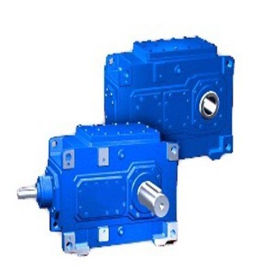
Let’s also address a common misconception: changing the gear ratio. A lot of people think that adding a gearbox is the easiest way to get more torque, and they’re not wrong—but it’s important to do it correctly. Torque is force times distance, so a gearbox with a reduction ratio of 10:1 will multiply the motor’s torque by 10, at the cost of speed. But here’s the catch: if your starting torque is too low for the load, a gearbox works, but you have to make sure the motor can handle the torque required at its input shaft. If you skip the previous steps and just add a gearbox to an underpowered motor, you might end up overloading the motor’s armature at startup, leading to premature wear or burnout. We had a client who tried this with a wheelchair motor, adding a 15:1 gearbox to a 12V motor that only had 1 Nm of starting torque. The gearbox gave them 15 Nm at the wheels, but the motor’s input torque was actually too high, and the brushes wore out in 3 months. Once we adjusted the motor’s winding to increase starting torque to 1.5 Nm, the brush life jumped to over 2 years. So gearboxes are a valid solution, but they’re a complement, not a replacement, for optimizing the motor itself.
Now, let’s talk about what not to do. Some designers think that just using a larger motor will fix the problem, but that’s almost always the most expensive option. A bigger motor uses more material, takes up more space, and draws more current at all times, which can be a problem for battery-powered applications like robotics or mobility devices. We see this mistake all the time: a client will come to us with a design that needs 3 Nm of starting torque, and they’re considering a 100W motor, when a 50W motor optimized for torque will do the job for half the cost and less than half the weight. Another mistake is ignoring brush wear. PMDC motors use brushes to transfer current to the armature, and higher current at startup means more sparking and brush wear. That’s why when we adjust windings or supply voltage to increase starting torque, we always check the brush rating to make sure it can handle the higher current. For example, if a standard brush is rated for 10A continuous, a 15A startup current is fine, but sustained 15A will cut brush life in half. We work with our clients to balance torque gains with component longevity, so they don’t have to trade performance for reliability.
DC Motor At the end of the day, increasing the starting torque of a PMDC motor is about understanding the tradeoffs between design, power, and cost. It’s not a one-size-fits-all solution; what works for a small robotic gripper won’t work for an industrial conveyor, and vice versa. As someone who’s been in the PMDC motor supply business for over 15 years, I’ve learned that the best solutions are the ones that are tailored to the specific application—whether that’s a simple start boost circuit, a custom magnet design, a winding adjustment, or a combination of all three. If you’re currently struggling with a PMDC motor that doesn’t have enough starting torque for your project, I’d encourage you to reach out to our team to discuss your needs. We can run performance simulations, build a prototype, and work with you to find the most cost-effective, reliable solution that fits your design. Whether you’re building consumer electronics, industrial equipment, or mobility devices, we have the expertise to help you get the starting torque you need without overdesigning or overspending.
References
- Boldea, I. (2016). Electric Machines: Steady-State Analysis and Design. CRC Press.
- Rashid, M. H. (2017). Power Electronics: Circuits, Devices, and Applications. Pearson.
- Fitzgerald, A. E., Kingsley, C., & Umans, S. D. (2003). Electric Machinery (6th ed.). McGraw-Hill.
- National Electrical Manufacturers Association (NEMA). (2020). Standard for Rotating Electrical Machines: DC Motors and Generators. NEMA Publication MG 1.
Zibo Auric Mechanical and Electrical Technology Co., Ltd.
As one of the leading permanent magnet dc moto manufacturers and suppliers in China, we warmly welcome you to buy advanced permanent magnet dc moto for sale here from our factory. All customized motors are with high quality and competitive price.
Address: B419, High-tech Entrepreneurship Park, High-tech Zone, Zibo City
E-mail: cui@auricmotor.com
WebSite: https://www.auricmotor.com/
